Experimental determination of flow ripple
Why is the flow ripple of a pump important?
Most hydraulic pumps (and other hydraulic machines) are based on the displacement principle. Hence, even in steady-state, the flow rate generated by such machines is always non-uniform with respect to time. The flow ripple generated by the pump interacts with the attached hydraulic system and causes pressure ripple. The amplitude and phase angle of the resulting pressure ripple depends on the impedance of the hydraulic system. If the flow ripple frequency matches one of the natural frequencies of the attached hydraulic system, resonance occurs. This can lead to very high pressure amplitudes which may impact the functionality or durability of the whole system. To avoid such potentially dangerous situations, it is vital to gather as much information about the transmission behaviour of the system and the flow ripple of the pump as possible.

How can the flow ripple be determined?
The flow ripple consists of two contributions:
- Kinematic ripple due to the pumping mechanism
- Dynamic ripple due to compressibility and leakage
For most pump types, the kinematic ripple can be calculated theoretically based on the pump's geometry. However, a satisfactory theoretical prediction of the dynamic ripple is typically not possible. Hence, experimental methods have to be employed.
Experimental determination of flow ripple
Since highly dynamic flow rate sensors are not readily available for the flow rates and pressure levels commonly encountered in hydraulic systems, the flow ripple has to be measured indirectly. At FLUIDON, this is done by measuring the pressure ripple in a measuring pipe attached to the pump (or motor) under investigation, see the following figure:
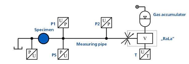
In general, the pressure distribution measured in the pipe (pressure sensor P1) results from the superposition of the pressure waves induced by the pump with reflections at the end of the pipe. This complicates the determination of the pump ripple since it is impossible to separate the contributions of the actual pump ripple and the reflections to the observed pressure signal. However, if the pipe would be of infinite length, no pressure waves would be reflected and hence the remaining pressure waves in the measuring pipe would be exclusively caused by the pump. In this case, the flow ripple can be calculated based on the measured pressure ripple. At FLUIDON, an infinitely long measuring line is approximately realised by the use of a so-called RaLa (German abbreviation for low-reflection line termination).
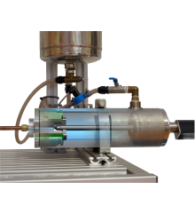
The RaLa consists of an adjustable orifice and a sufficiently large hydraulic capacity. If the orifice is adjusted correctly to match the impedance of the measuring pipe, the pressure waves induced by the specimen are not reflected at the pipe end. In this case, the hydraulic behaviour of the approximately 1 m long measuring pipe changes to that of a pipeline of infinite length and the flow ripple can be calculated based on the pressure readings. In order to ensure that the orifice setting is correct, the measuring pipe is fitted with a second pressure transducer P2.
Applications
For industrial pumps, typically the pulsations on the high pressure side are of interest, as they can excite the system and lead to undesired vibrations. For this application, pressure proof RaLas are used which can withstand pressures of up to 400 bar. Special designs are capable of pressure levels of up to 2,000 bar. The nominal flow rate vary between a few litres per minute and 300 l/min.
In the automotive sector, however, the focus is also on pulsations on the suction side, since excitation of the pump's supply line can lead to noise or structural vibrations. The design of these RaLas is adapted to the special requirements of low-pressure operation. The pressure levels can be as high as 100 bar.
Our test benches
For both applications, FLUIDON builds pressure level and flow rate adapted RaLas both for its own applications and for customer orders.
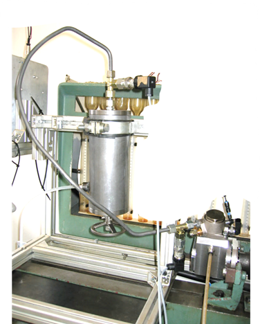
High-speed test rig for measuring high-pressure fuel injection pumps
- Maximum RPM: 7,500 1/min
- Maximum drive torque: 30 Nm
- Operating pressure up to 2000 bar
- Operating fluid: non-inflammable Diesel fuel replacement fluid
- "Beckhoff" data acquisition with up to 40 kHz sampling rate
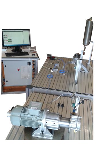
Test rig for measuring flow ripple on the suction side
- Maximum RPM: 3000 1/min
- Operating pressure up to 8 bar
- Operating fluid: on demand
- "Beckhoff" data acquisition with up to 40 kHz sampling rate
- Automated test rig control