Four-pole test rig for determining the transmission behaviour of hydraulic components
Why is the transmission behavior of components important?
During a vibration analysis of piping systems, the identification of critical natural frequencies and associated eigenmodes is most important. Which eigenmodes are formed at which frequencies is determined by the boundary conditions of the pipelines (e.g. "open" or "closed") and the transmission behaviour of the pipes.

How is the transmission behavior of components characterized?
The transfer behavior of simple elements can be characterised - as known from control engineering - by a so-called transfer function. The transfer function indicates the ratio of the output to the input variable of a system in the frequency domain. The transfer function is generally frequency-dependent and - since phase angles between output and input variables are typically different from zero - usually complex. Only for relatively simple elements, such as an ideal inductance, one input and output variable is sufficient for a complete state description. In hydraulic systems, at least two (in the case of pneumatics or thermohydraulics even three) variables are required for a complete description of the state of an input or output. Typically, the variables pressure and volume flow are selected for this purpose. Since there is a total of two input and two output variables, the transfer function can no longer be a scalar function. In this case, the transfer function must be extended to a transfer matrix with 2 ∙ 2 = 4 entries.
What can be calculated from the transfer matrix?
If the transmission matrix is known, the positions of the resonance and absorber frequencies of the respective component can be calculated for all possible boundary conditions. In addition, the transmission loss can be determined from the entries in the transmission matrix, which provides information about the frequency-dependent transmission and attenuation behavior of the specimen. The greater the transmission loss of a component, the more it impedes the transport of vibration energy. The four-pole transmission matrix can also be used to parameterise time domain models of hose assemblies and other components with complex material behavior. An optimisation calculation determines the model parameters such that the dynamic behavior of the model corresponds to that of the original. If the component under investigation is used as a pipeline termination, the input impedance of this termination can also be determined from the four-pole matrix.
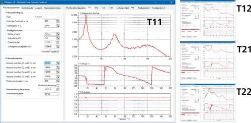
Elements T11, T12, T21 and T22 of the four-pole transfer matrix of a specimen, calculated with the in-house analysis tool
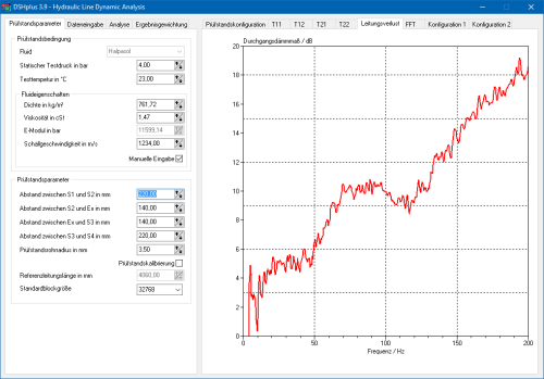
Transmission loss of a specimen, calculated with the in-house analysis tool
How can the transfer matrices of components be determined?
In the case of components with simple geometry and easy to describe material behaviour (e.g. a steel pipe), the transfer matrix can be calculated in a purely theoretical way by solving the fluid mechanical conservation equations. In practice, the successful application of this approach is hampered by the fact that the material parameters of many of the pipe and hose materials used in fluid power systems (e.g. polyamides or fluorinated rubbers) are not precisely known. The unknown properties of these wall materials can also depend on the frequency (viscoelasticity) or on the pressure and temperature, which introduces additional uncertainties. If, in addition, the geometry of the component is so complex that the resulting velocity and pressure distributions cannot simply be calculated with one-dimensional wave theory, the theoretical approach is completely doomed to failure. This can be remedied by quick and inexpensive experimental determination of the four-pole transfer matrix by using the actual component.
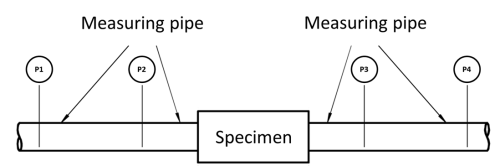
Experimental determination of transfer matrices
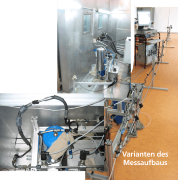
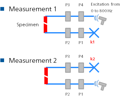
FLUIDON has its own test bench for the experimental determination of the transfer matrices of hydraulic components. The measurement is carried out according to the "two source" method. For the measurement, the specimen's input and output flanges are connected to measuring pipes. Each of the two measuring pipes is equipped with two pressure sensors. In two separate measurements, the specimen is excited from one side by an external pulsation source (e.g. a pump or a valve). The resulting pressure waves are recorded by a total of four pressure sensors. By using measuring pipes with known transmission behaviour, a frequency domain flow rate can be calculated from the fourier-transformed signals of two adjacent pressure sensors. Thus, for each of the two measurements, the pressures and flow rates at the outlet and inlet flange of the component to be tested can be determined, which are linked by the unknown four-pole transmission matrix of the specimen. This corresponds to an equation system with four equations and four unknowns (the elements of the transfer matrix), which can be resolved unambiguously for the elements of the transfer matrix. The entire evaluation is carried out conveniently by the in-house DSHplus analysis tool.
A possible frequency dependence of the properties of the wall material is automatically taken into account in the measurement method used. If the properties of the wall material also depend on pressure or temperature, the measurement must be performed at different operating points. In this case, a different transfer matrix results for each pressure or temperature level. FLUIDON has the capability to measure transfer matrices at stationary pressure levels ranging from 0 to 8 bar (relative) and in the temperature range from - 20 °C to 50 °C. Measurements at higher pressures and temperatures are available on request.
FLUIDON offers all services related to the experimental determination of the transfer matrix - from measurement and evaluation to interpretation and processing of results - from a single source.