


Test bench for measuring hydraulic input impedances
What is the input impedance and why is it important to know it?
For a given excitation (e.g. due to pump flow ripple), the occurrence of resonance effects in a fluid power system is essentially determined by the position of the natural frequencies and the shape of the associated eigenmodes. The eigenmodes and natural frequencies of the line system in turn depend on the boundary conditions at the pipe ends. The boundary conditions can be distinguished into two extreme cases:

For a so-called "closed end", a flow rate is imposed. This boundary condition is suitable to model e.g. a pipe end which is closed by a blocked valve. The "fixed" velocity leads to the formation of a velocity node and thus a pressure antinode. An "open end" exists when a pressure is specified at the pipe end. This boundary condition is used, for example, when a pipeline discharges into an open tank, thus "communicating" with the environment. In this case, the ambient pressure is applied to the end of the pipe so that a pressure node is formed.
Many fluid power systems have pipe terminations that cannot be clearly assigned to either of the two extreme cases presented above. Such "undefined" line terminations exist, for example, when pipes are terminated by hydrostatic pumps, motors or passive components with complex geometries. The principle-based existence of constantly moving displacement elements (and valves, if applicable) in hydrostatic machines prevents a representation by simple hydraulic elements such as pipelines or resistors. Even immobile components with not elementarily predictable stiffnesses (e.g. corrugated hoses or filter housings) or branched inner channels introduce great uncertainties in the termination modelling and thus in the resulting vibration analysis.
If systems with such termination are nevertheless to be subjected to a realistic one-dimensional vibration analysis, the use of a dynamically equivalent substitute system has proved to be successful. A substitute system is an arrangement of basic hydraulic elements (e.g. resistances and capacities) which are parameterised in such a way that their interaction achieves the same dynamic effect on the system to be terminated as the actual component. For example, the termination behaviour of many hydrostatic pumps and motors can be represented by a hydraulic Helmholtz resonator (series connection of a pipe and a volume).
To determine the parameters of the substitute system, knowledge of the dynamic termination behaviour of the actual component is required. The termination behaviour can be quantified by the so-called input impedance. The input impedance indicates the relationship between the pressure and flow ripple at the flange of the respective component.
In general, the input impedance of a component is frequency-dependent and complex since the phase angle between pressure and flow ripple is typically non-zero. The frequency response of the input impedance of real components can also be pressure dependent due to non-linear material or component behaviour, so that in this case a different impedance curve (and correspondingly, a differently parameterised substitute model) results for each steady-state pressure level.
How can the input impedance be determined?
Theoretically, it would be possible to determine the input impedance of complex termination components by coupled, three-dimensional CFD and structural mechanics simulations. Due to the long calculation times, however, impedance determination according to this principle would lead to an unacceptable expenditure of time and money. On the other hand, direct measurement of the input impedance on the actual component is faster and cheaper.
How can we measure the input impedance?
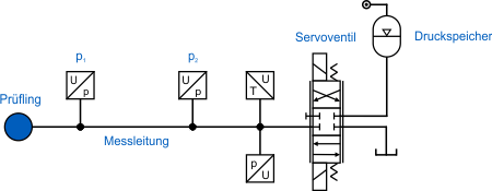
FLUIDON uses the secondary source method to measure the input impedance. In this method, standardized in ISO 10767-1, the component whose input impedance is to be determined is connected to a measuring pipe and excited to oscillate in the frequency range of interest by a pulsation source located at the other end of the pipe (the eponymous secondary source). In our test bench, the excitation is realised by a directional valve which is controlled by a sinusoidal input signal at a constant offset signal. During the course of the measurement, the frequency of the signal increases in from 0 Hz to the maximum frequency. The system pressure is adjusted via the accumulator and kept constant during the measurement using a pressure regulator. The resulting oscillations are recorded by two pressure sensors in the measuring pipe. From the Fourier-transformed signals of the two pressure sensors, the pressure and flow rate oscillations in the middle between the two sensors can be calculated. Since the transmission behaviour of the measuring pipe is known, the pressure and flow rate at this point can be used to compute the corresponding quantities at the flange of the specimen. The input impedance of the component is then calculated as the ratio of pressure and flow rate oscillations at the flange.
Test bench specifications
- Maximum excitation frequency: 400 Hz
- System pressure:
- Low pressure up to 8 bar
- High pressure up to 250 bar
- "Beckhoff" Data acquisition up to 40 kHz
- Automated test bench control
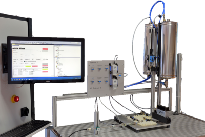
In-house "secondary source" test bench
Results
The input impedance can be used to parameterise a substitute system after the measurement. Since the impedance of simple hydraulic elements (and their interconnection) can be calculated theoretically, the parameters (e.g. lengths and diameters) of the substitute system can be calculated automatically by an optimization in the frequency domain.
The measured input impedance of a component can also be used to draw conclusions about its termination behaviour: If the measured input impedance is significantly greater than the characteristic impedance of the terminated pipeline, the component acts as a closed end. If, on the other hand, the input impedance is significantly lower than the pipe impedance, the component under investigation acts like an open end (e.g. a large tank). If the input impedance equals the characteristic impedance of the pipeline, pressure and flow waves are practically not reflected at the interface between pipe and termination, which corresponds to a reflection-free line termination. Since the input impedance of the specimen usually changes with the frequency, one and the same component can act like an open end at one frequency, but correspond to a closed pipe termination at another frequency.
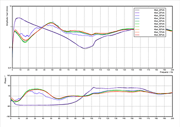
The figure to the left shows an example of the input impedance curve of a tank measured at FLUIDON. The tank is divided into two sections by a check valve (CV). The input impedance is decomposed into amplitude (top) and phase (bottom) for a clear presentation.
- If the RV is closed (overrun mode of the combustion engine), the input impedance is only determined by the first section (seen from the tank flange).
- The RV is open when the combustion engine is working actively and needs to be supplied with fuel.
- Whenever the driver "leaves the throttle", the input impedance of the tank changes.
This example illustrates the necessity of measurements at different operating points if non-linear system behaviour is to be expected: Opening or closing of the CV leads to a drastic change in the input impedance of the tank, which in turn results in a changed vibration situation for the connected line system.