Introduction & Physical Basics
Cavitation phenomena cause increased noise levels and can lead to severe, life-limiting wear of components. Since there is no such thing as "the" cavitation, a distinction must be made between different types of cavitation.
Types of Cavitation
In the following paragraphs, the different types of cavitation are presented and the associated effects on the behaviour of hydraulic systems are examined. These phenomena, whose occurrence usually depends on the operating point, can nowadays already be analysed during the design phase by 1D simulation, such that the tendency of a system to cavitate can be checked before manufacturing.
The explanation of the individual types of cavitation is based on the example of hydraulic flow through a generic resistor. As an introduction, the situation without cavitation is first discussed.
The content of this page can be viewed in Webinar form by clicking on the adjacent video.
Cavitation-free flow
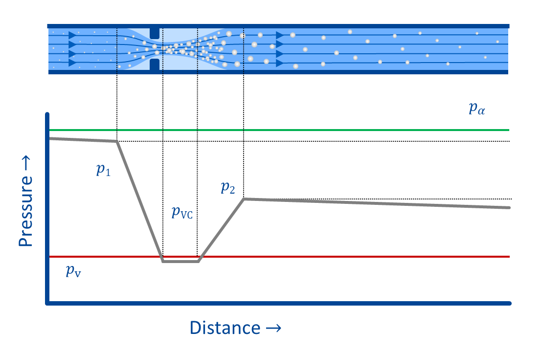
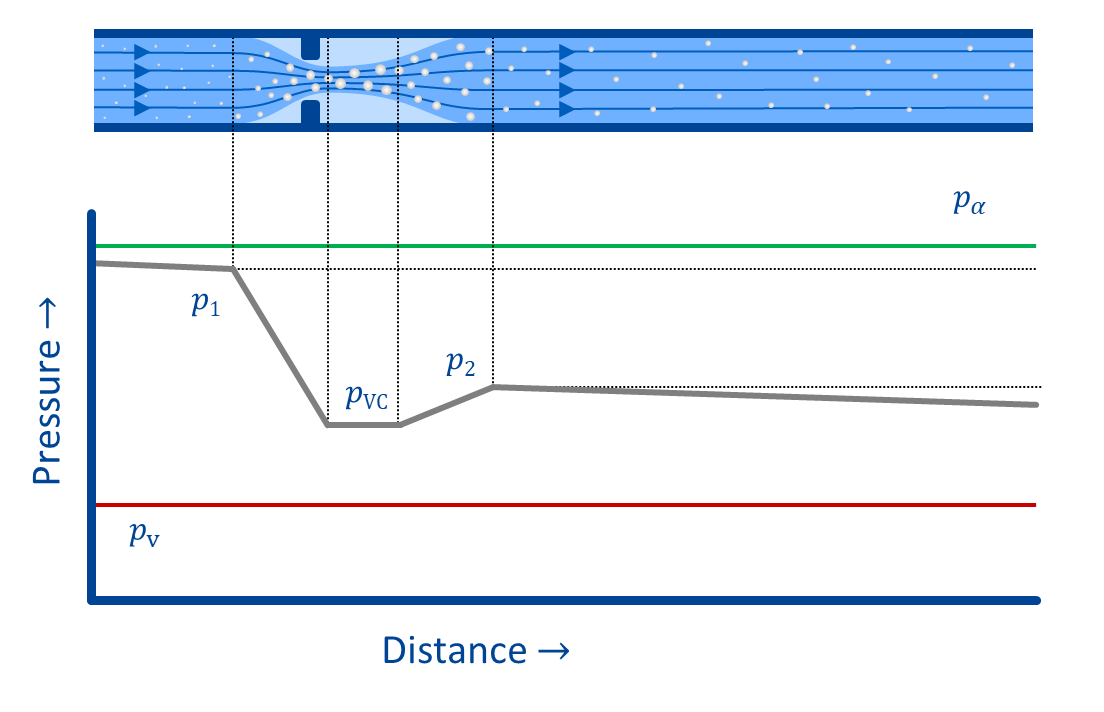
The liquid flowing into the resistor (index "1" in the adjacent figure) has a certain total energy, which consists of the additive contributions of potential energy (proportional to the static pressure) and kinetic energy (proportional to the square of the fluid velocity).
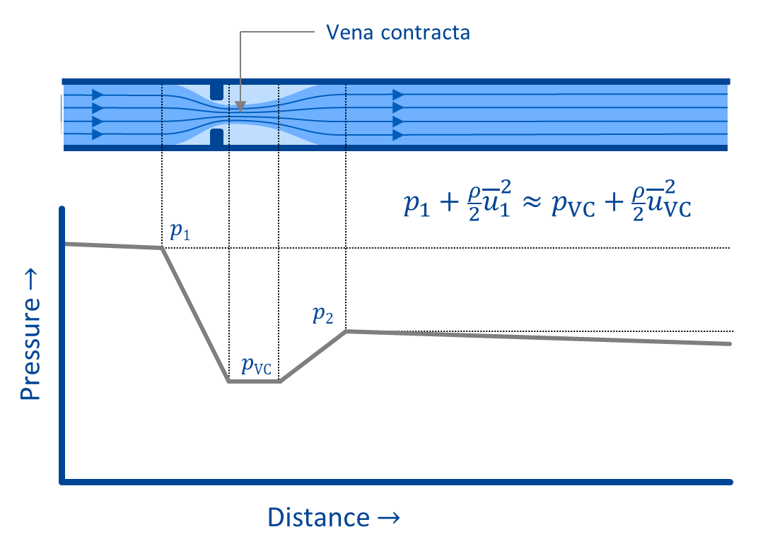
According to Bernoulli's law, the total energy along a streamline is constant. The resistor reduces the cross-sectional area through which the flow passes, such that the fluid velocity increases - the static pressure decreases accordingly. The cross-sectional area with the highest velocity – the so-called "vena contracta" – therefore corresponds to the point of lowest static pressure.
After the fluid has passed the vena contracta, the fluid velocity decreases again and the static pressure increases correspondingly. However, due to losses, the static pressure behind the resistance will be lower than the inlet pressure.
In general, an increase in the flow rate through the resistor leads to an increase in pressure loss. This rule also holds true vice versa: If the applied pressure difference increases, the flow rate increases. However, experience shows that there is an upper limit to this dependence, i.e. an increase in the pressure difference does not lead to an increase in flow rate above a certain value. Why is that?
Higher flow rates lead to higher velocities and thus lower pressures in the vena contracta. If the local pressure drops below a certain level, phenomena generally known as "cavitation" occur. Depending on the physical mechanism, three types of cavitation can be distinguished: Vapour, gas and pseudo cavitation. First, vapour cavitation is discussed.
Vapour Cavitation
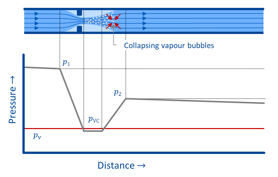
If the local pressure in the vena contracta drops below the temperature-dependent vapour pressure of the liquid, vapour bubbles form. After flowing through the narrowest cross section, the bubbles collapse almost instantaneously as the local pressure exceeds the vapor pressure again (see adjacent figure). The phenomenon of pressure-dependent formation and subsequent collapse of vapour bubbles is known as vapour cavitation (cavitation in the strict sense).
In most cases, vapour cavitation is an undesirable event, as it limits the flow rate through valves and resistors (known as "choking") and causes noise, erosive component damage and pipe vibrations. The direct effects of vapour cavitation are usually limited to the areas with p < pv and in their immediate vicinity.
Gas Cavitation
Even if the local pressures do not drop to values below the vapour pressure, a flow pattern similar to that of vapour cavitation can often be observed.
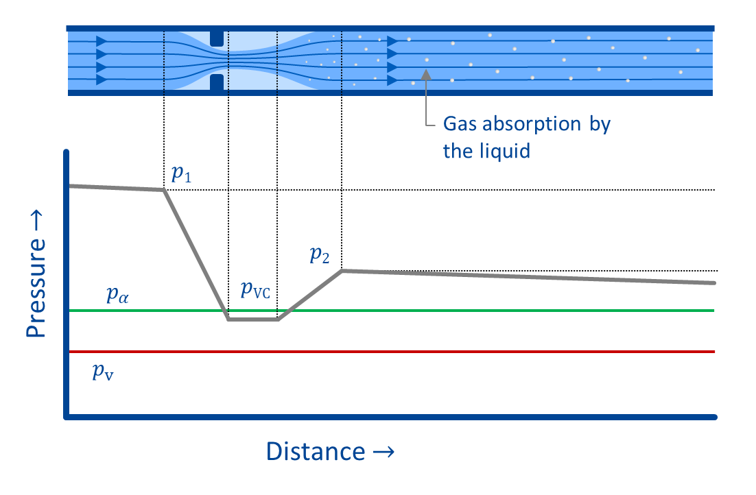
Liquids exposed to air or other gases can absorb a certain amount of the respective gas. The ability to dissolve gases decreases with decreasing pressure (Henry's law). When a liquid loaded with dissolved gas passes through the resistor and the pressure in the vena contracta falls below a certain pressure (here referred to as pα), part of the dissolved gas is released ("desorption").
In contrast to vapour cavitation, however, the flow downstream of the resistor remains initially loaded with gas bubbles, since the absorption back into the liquid typically takes considerably longer than the desorption. This can lead to problems, since even small amounts of undissolved gas can significantly alter the fluid properties. Since the bubbles are transported along with the fluid flow, even areas not prone to cavitation can therefore suffer from the effects of cavitation.
Pseudo Cavitation
Even without the release of previously dissolved gas, a cavitation-like phenomenon can occur.
If the upstream liquid already contains gas bubbles, their volume increases almost instantaneously as the pressure within the resistor (or at another point in the flow field) decreases.
After reaching zones of higher pressure, their volume shrinks again. The phenomenon of pressure-dependent bubble growth and shrinking without absorption or desorption is referred to as pseudo cavitation.
Mixed Cavitation
In practical applications, all three cavitation mechanisms typically occur simultaneously. For mineral oils, gas cavitation generally dominates, whereas in applications with water-based pressure media, vapour cavitation is often most pronounced due to their comparatively low air dissolving capacity.
Most hydraulic fluids are loaded with a certain amount of dissolved and undissolved gas. Due to lower pressures at the vena contracta (or other constrictions in the system), the volume of undissolved gas will increase (pseudo cavitation). If vapour cavitation also occurs, the newly formed bubbles will contain certain amounts of the previously dissolved gas in addition to the vapour of the liquid.
When pressures p > pv are reached, the vapour content of the bubbles disappears quickly, but the gas bubbles remain – as with pure gas cavitation, the gas requires some time to dissolve back into the liquid. The bubbles migrate further downstream with the flow, potentially causing problems due to altered fluid properties.