Reflexion von Druckwellen in Leitungssystemen
Verändert sich die charakteristische Impedanz einer Leitung entlang der Ausbreitungsrichtung einer Welle, so entstehen Reflexionen. Im Allgemeinen führt eine Reflexion dazu, dass zwei neue Wellen erzeugt werden - eine transmittierte und eine reflektierte Welle. Ursachen für Impedanzänderungen können sein:
- Geschlossene Enden
- Offene Enden
- Änderungen des Leitungsdurchmessers
- Änderungen des Leitungswerkstoffs (z. B. von Stahl auf Schlauch)
- Punktartige Strömungswiderstände wie Blenden, Ventile etc.
- T-Stücke und Abzweige
- Dichte- und Schallgeschwindigkeitsänderungen (z. B. durch thermische Effekte)
Reflexionsfaktor
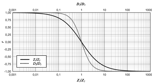
Das Verhältnis von reflektierter Druckwelle \(\delta p_r\) zu eintreffender Druckwelle \(\delta p_e\) wird als Reflexionsfaktor \(r\) bezeichnet. Es lässt sich aus den charakteristischen Impedanzen vor (\(Z_1\)) und nach (\(Z_2\)) dem Impedanzsprung berechnen: $$r = \frac{\delta p_r}{\delta p_e} =\frac{Z_2 - Z_1}{Z_2 + Z_1}.$$ Der Verlauf des Reflexionsfaktors \(r\) über dem Impedanzverhältnis \(Z_1/Z_2\) bzw. über dem Durchmesserverhältnis \(D_2/D_1\) ist in der folgenden Abbildung dargestellt:

Offenes Ende
Da das Impedanzverhältnis \(Z_1/Z_2\) für den Spezialfall eines offenen Endes gegen Unendlich strebt, ergibt sich der Reflexionsfaktor zu \(r \approx -1\). Die reflektierte Welle ist also betragsmäßig genau gleich der eingehenden Welle. Das andere Vorzeichen deutet an, dass die reflektierte Welle genau entgegengesetzt zur ursprünglichen Welle läuft. Die zurücklaufende Welle (Summe aus reflektierter und eingehender Welle) ergibt sich für diesen Fall zu Null.
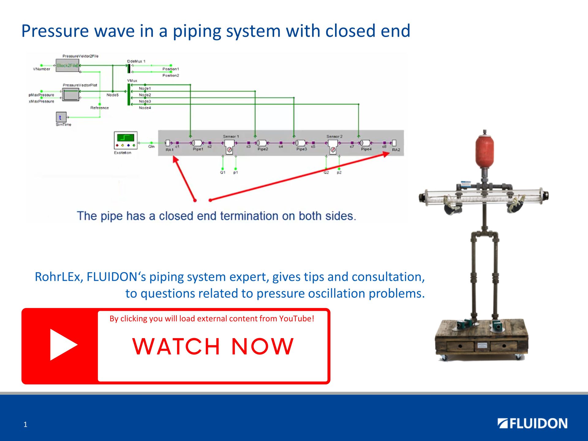
Geschlossenes Ende
Da das Impedanzverhältnis \(Z_1/Z_2\) für den Spezialfall eines geschlossenen Endes gegen Null strebt, ergibt sich der Reflexionsfaktor zu \(r \approx 1\). Die reflektierte Welle ist also sowohl bezüglich ihres Betrags als auch ihres Vorzeichens gleich der eingehenden Welle. Die zurücklaufende Welle (Summe aus reflektierter und eingehender Welle) ergibt sich für diesen Fall zu \(2\delta p_e\).
Reflexion einer Druckwelle am geschlossenen Ende eines Rohres
A pressure oscillation resonance in a pipe closed on both sides, referred to as a closed tube resonance or closed-end resonance, occurs when sound waves within the pipe generate a standing wave pattern due to wave reflections at the closed ends. Here are the key points to understand about it:
-
Standing waves: When a sound wave propagates through a pipe closed on both ends, it undergoes reflection at each end. The resulting interference between the incoming and reflected waves gives rise to a stationary pattern known as a standing wave. Within the pipe, specific locations exhibit points of minimal displacement (nodes) and points of maximal displacement (antinodes).
-
Resonance frequencies: Closed pipe resonance transpires at distinct frequencies associated with the fundamental frequency and its harmonics. The fundamental frequency represents the lowest resonant frequency at which the fluid within the pipe can vibrate. The higher harmonics are integer multiples of the fundamental frequency.
-
Pipe length and resonance: The length of the pipe determines the wavelengths that can fit within it, thereby establishing the frequencies at which resonance occurs. The fundamental frequency in a pipe with both ends closed is inversely proportional to the pipe length. Mathematically, the fundamental frequency (f) is expressed as f = a / (2L), where a represents the speed of sound in the medium and L denotes the length of the pipe.
-
Node and antinode positions: In closed pipe resonance, the closed ends of the pipe function as nodes for the flow, indicating no displacement at these points but as antinodes for the pressure. The positions of nodes and antinodes within the standing wave pattern depend on the resonance mode (fundamental or harmonic) and the pipe length.
-
Sound production: Pressure oscillations occurring within the pipe, resulting from the standing waves, lead to the generation of sound. The pipe acts as a resonator, amplifying specific frequencies dictated by its length.
It is essential to note that the information provided here assumes idealized conditions and simplifications. Real-world scenarios may involve additional factors, such as pipe geometry, wall properties, and damping effects, which can influence the precise behavior of pressure oscillation resonances in closed pipes.
Reflexion einer Druckwelle am offenen Ende eines Rohres
In a pressure oscillation resonance scenario in a pipe that is open at one end and closed at the other, several factors come into play. The phenomenon involves the interaction between the acoustic waves and the geometry of the pipe, leading to the amplification of specific frequencies. Here are some key aspects to consider:
-
Pipe Length: The length of the pipe determines the wavelengths of the resonant frequencies that can be established. A quarter-wavelength resonance occurs when the length of the pipe is equal to one-fourth of the wavelength of the desired resonant frequency.
-
Harmonic Frequencies: The resonance phenomenon can occur at various harmonics of the fundamental frequency. Each harmonic represents a multiple of the fundamental frequency, such as three times, or fife times the fundamental frequency, and so on.
-
Standing Waves: When a pressure oscillation of a specific frequency reaches the closed end of the pipe, it reflects back and interferes with the incident wave. This interference results in the formation of standing waves, where points of maximum and minimum pressure, known as nodes and antinodes, are established along the length of the pipe.
-
Resonant Frequencies: Resonant frequencies are the frequencies at which the standing waves are most pronounced. These frequencies correspond to the natural frequencies at which the pressure oscillations in the pipe reinforce each other, resulting in a significant increase in the amplitude of the waves.
-
Node and Antinode Distribution: The distribution of nodes and antinodes depends on the mode of the standing wave formed. In the fundamental mode (first harmonic), there is, if pressure is considered, one ode at the open end of the pipe and one antinode at the closed end. At higher harmonics, the number of nodes and counter-nodes increases accordingly; these are then located inside the pipe.
It is essential to note that the information provided here assumes idealized conditions and simplifications. Real-world scenarios may involve additional factors, such as pipe geometry, wall properties, and damping effects, which can influence the precise behavior of pressure oscillation resonances in pipes.

Durchlauf einer Druckwelle durch ein reflexionsarmes Leitungsende
A low reflection end condition refers to a situation where the pipe termination minimizes wave reflections, allowing smooth transmission of pressure waves.
When examining pressure pulsation in such a pipe, several key aspects should be considered:
-
Wave Propagation: Pressure pulsation in a pipe can be understood as the propagation of pressure waves generated by various sources, such as pumps, compressors, or fluid flow disturbances. These waves travel through the fluid medium inside the pipe.
-
Wave Reflection: In a low reflection end condition, the termination of the pipe is designed to minimize wave reflections. Ideally, the termination has characteristics that prevent waves from bouncing back into the pipe. This feature reduces the occurrence of pressure pulsations caused by wave reflections.
-
Impedance Matching: The low reflection end condition often involves impedance matching, where the characteristic impedance of the termination closely matches that of the pipe. This matching minimizes the mismatch between the termination and the pipe, reducing the potential for wave reflections.
-
Pressure Attenuation: Despite the low reflection end condition, some pressure pulsations may still exist due to various factors, such as fluid compressibility, pipe friction, or flow instabilities.
By considering these aspects, engineers and researchers can assess the pressure pulsation behavior in pipes with low reflection end conditions, allowing for better design and optimization of fluid systems.

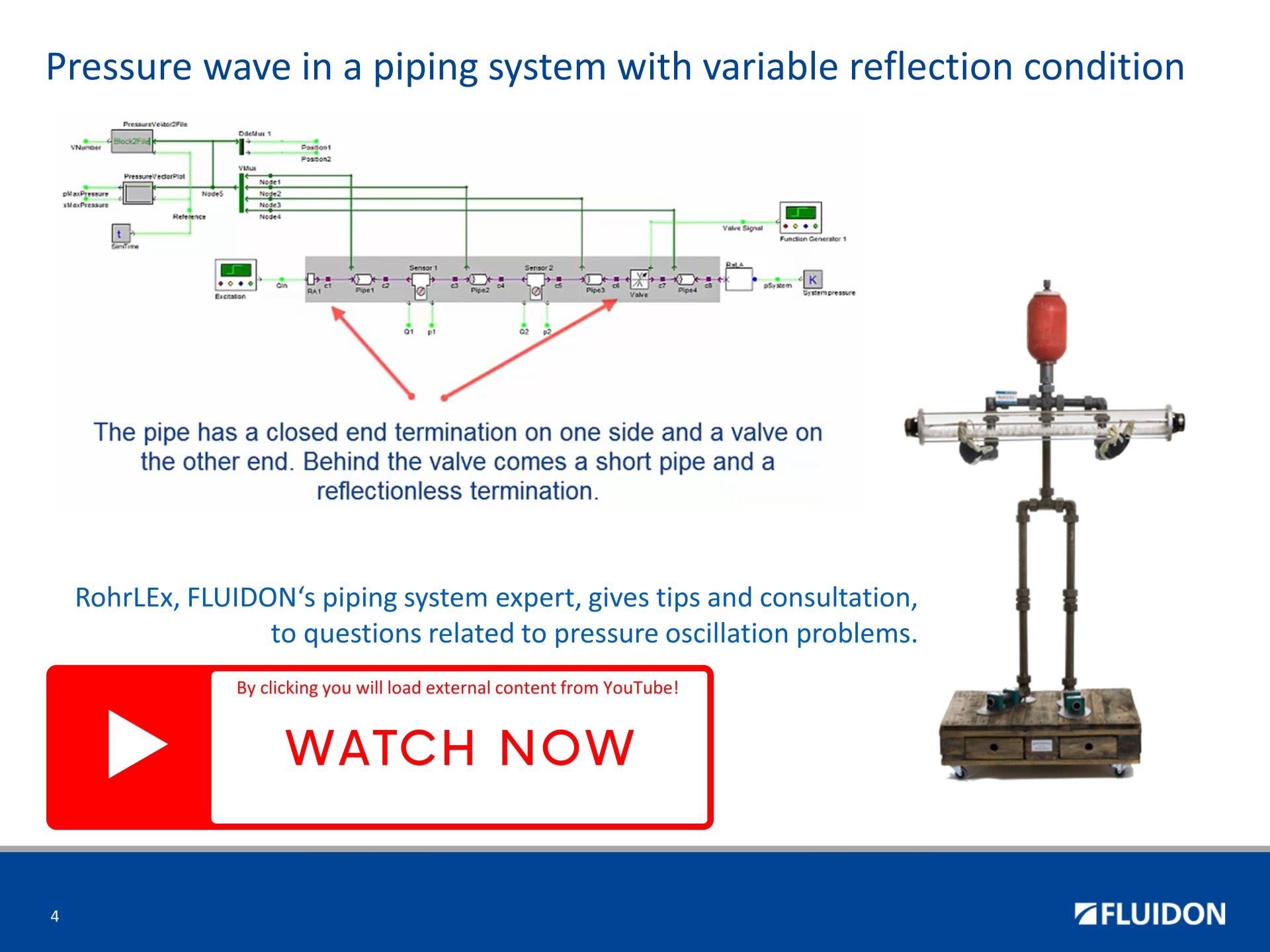
Durchlauf einer Druckwelle durch ein Leitungsende mit variabler Abschlussimpedanz
In a pipe with variable termination impedance, such as a hydraulic valve, the phenomenon of pressure wave reflection occurs when a pressure wave traveling along the pipe encounters a change in impedance at the termination point.
Here are some key points to consider regarding pressure wave reflection in such a system:
-
Termination Impedance: The termination impedance refers to the characteristic impedance of the hydraulic valve or any other component at the end of the pipe. It represents the opposition to the flow of pressure waves and depends on factors such as valve geometry, material properties, and operating conditions.
-
Incident and Reflected Waves: When a pressure wave propagates along the pipe and reaches the termination point, it encounters the change in impedance. This change causes a portion of the wave to be reflected back into the pipe as a reflected wave. The remaining portion continues past the termination point as the transmitted wave.
-
Reflection Coefficient: The reflection coefficient quantifies the ratio of the amplitude of the reflected wave to that of the incident wave. It is influenced by the mismatch between the characteristic impedance of the pipe and the termination impedance. A reflection coefficient of zero indicates complete transmission, while a value of one indicates complete reflection.
-
Effects of Reflection: The reflection of pressure waves can lead to various effects, including pressure oscillations, energy losses, and potential damage to the system. These effects depend on the magnitude of the reflection coefficient, the wave frequency, and the characteristics of the termination impedance.
-
Standing Waves: In cases where the incident and reflected waves interfere constructively or destructively, standing waves can form within the pipe. Standing waves are stationary patterns of high and low pressure regions that can cause pressure variations and affect the system's performance.
-
Impedance Matching: Proper impedance matching between the pipe and the termination impedance can minimize pressure wave reflections. By adjusting the termination impedance to match the characteristic impedance of the pipe, the reflection coefficient can be reduced, leading to improved system efficiency and reduced pressure fluctuations.
Through careful consideration of impedance matching and system dynamics, engineers can mitigate the negative effects of pressure wave reflections and enhance the overall performance of hydraulic systems. A theoretical example of a matched impedance is presented here. A FLUIDON's Rala is practical example of a matheched impedance.
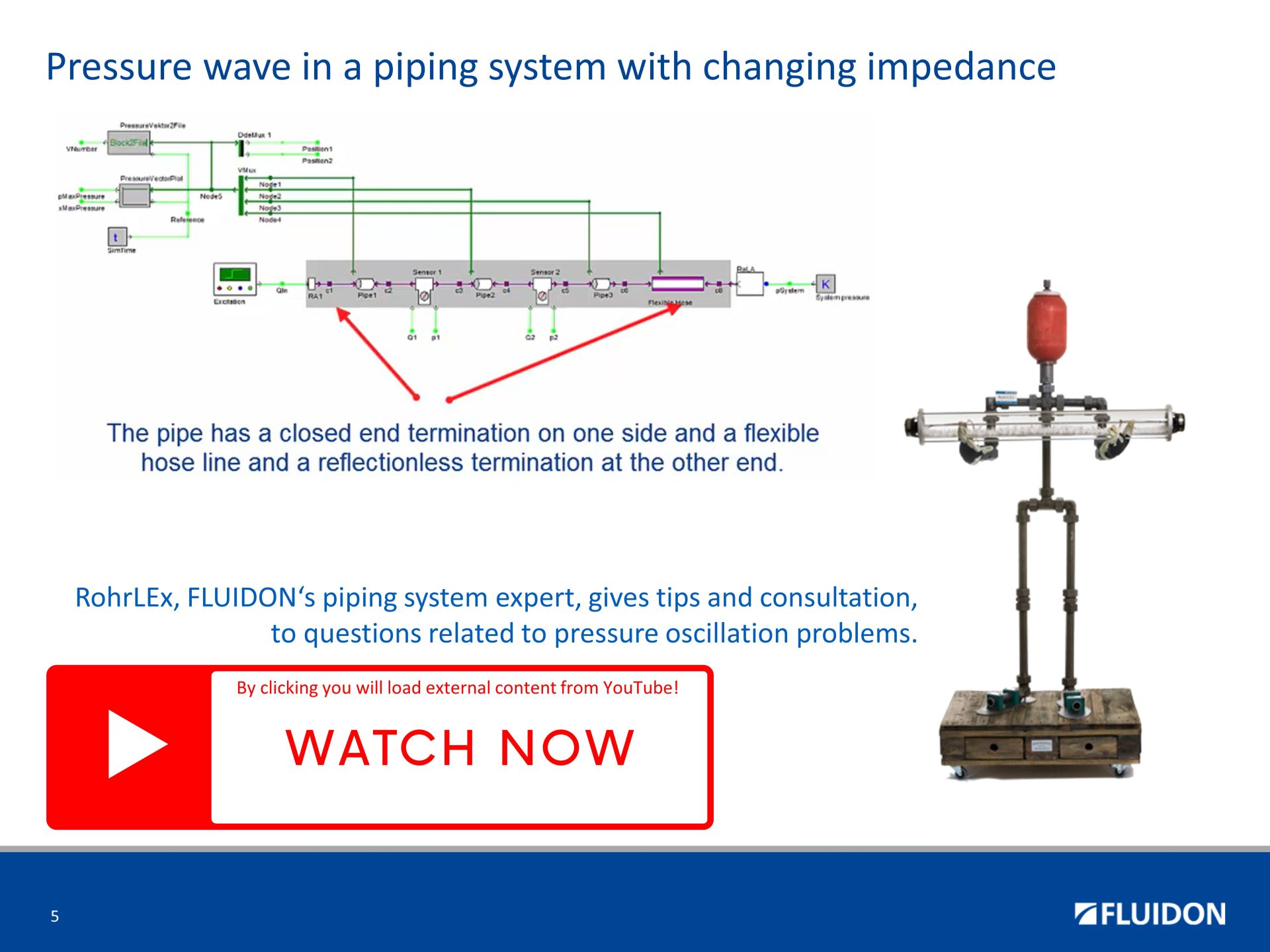
Reflexion einer Druckwelle an der Impedanzänderung zwischen Rohr und flexiblem Schlauch
When a pressure wave travels through a pipe and encounters a change in pipe geometry or a change in pipe material, the phenomenon of reflection occurs. The reflection of the pressure wave can be explained by the principles of fluid dynamics.
- When the pressure wave reaches the area of change (diameter, wall thickness, material properties), a portion of the wave is transmitted through, while another portion is reflected back towards the source. The reflection occurs due to the change in the acoustic impedance. The acoustic impedance is determined by the product of fluid density and sounic velocity devided by the cross sectual area.
- The magnitude and nature of the reflection depend on various factors, such as the angle of incidence, the magnitude of the change in diameter, and the properties of the fluid.
- In general, a sudden expansion (increase in diameter) leads to a reflection of a negative pressure wave, while a sudden contraction (decrease in diameter) causes a positive reflection.
- The reflected wave propagates back towards the source and interacts with the incident wave. The interaction results in interference patterns, where the superposition of the incident and reflected waves leads to constructive or destructive interference. The specific interference pattern depends on the phase relationship between the incident and reflected waves.