


Library for the simulation of fluid-structure interaction (FSI)
Why is a FSI library needed?
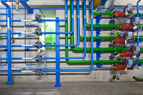
The computer assisted design of fluid power systems is often based on the assumption of infinitely stiff pipelines. When calculating short metal pipes with small internal diameters and large wall thicknesses, this simplification is - in general - reasonable. However, this assumption is usually not justified for slender pipes with large spans and pipes with changes of direction (elbows, elbows), where it may lead to incorrect predictions about the operating behaviour or service life of the system. Such situations can be found, for example, in fuel supply lines in passenger cars, hydraulic pipes in aircraft and many delivery lines in process engineering. In such systems, the movements of pipe walls of finite stiffness and the fluid inside the pipe influence each other, which can result in undesirable phenomena such as noise, pipe beating or even fatigue failures. The new FSI library extends the tried and tested pipe models of DSHplus so that these interactions can be taken into account during the 1D hydraulic simulation.

Degrees of freedom of the pipeline taken into account by the numerical model
What are the features of the FSI library?
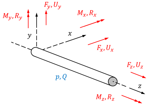
The pipe models of the conventional DSHplus pipe library solve the momentum and continuity equation of the fluid in order to determine the temporal and spatial development of the state variables pressure p and volume flow Q. For the FSI components, twelve additional equations are solved for the six degrees of freedom (with one force and one displacement quantity each) of the pipe wall. The degrees of freedom of the pipe wall considered are shown in the adjacent figure. The 14 equation model of the FSI library allows the consideration of the following phenomena:
- Torsion of pipelines around their longitudinal axis
- Bending of the pipelines where the inertial mass of the fluid and shear deformation are taken into account
- Elastic or viscoelastic pipe supports, e.g. by clamping units
- Coupling of axial stresses in the pipeline with the pressure of the fluid (POISSON effect)
- Exchange of forces and moments at elbows
Library content
The FSI library provides the following components to model various system configurations:
- Pipe
- Elbow
- Pipe clamping with elastic or viscoelastic material behaviour
- Adjustable resistor (to model valves etc.)
- Line termination with prescribed pressure ("open end")
- Line termination with prescribed mass flow ("closed end")
Postprocessing
If the pressure vibration analysis is to be used primarily for the evaluation of component loads, the pipe's internal mechanical variables (forces, moments and displacements) can be visualized as a 3D diagram just like the pressure pulsation plot. Since the diagram depicts the stretched length of the pipeline on one axis, the designer gets an overview of whether fatigue-sensitive system components (e.g. welded joints) are located in areas of high dynamic loads. The frequency of the load can be read off on the other axis. The hydraulic natural frequencies of the pipe are indicated in the diagrams by dashed horizontal lines. Vertical lines mark the positions of the fixing points and the pipe bends.
Further information on fluid-structure interaction can be found in our article "Dynamic Load Cases in Piping Systems - Part III" (in German), which can be downloaded here.